My 2000 Whitehill XL1
The Assembly
Click Images for a closer look.
Finally.
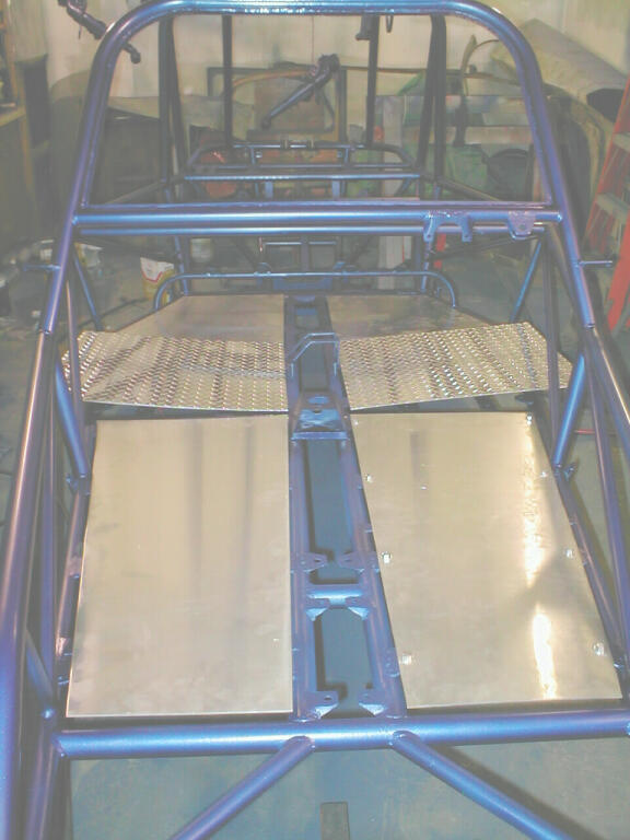
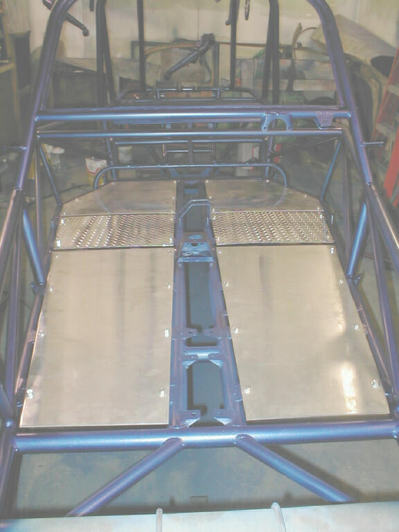
The floor panels that I bought with the frame only included the front and rear quarters.
I wanted panels under and between the seats. I bought .100 diamond plate and I think it adds a nice contrast.
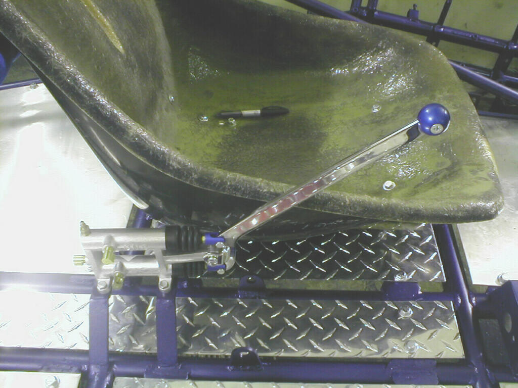
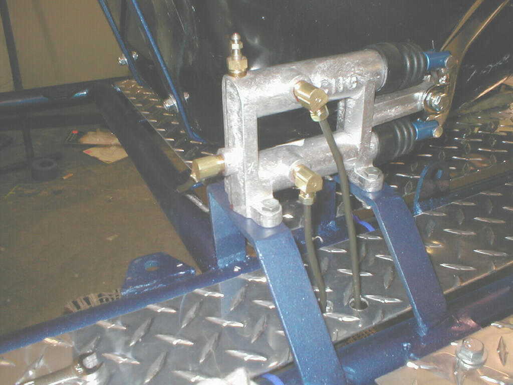
Here you see the drivers seat, all floor panels, hydraulic pedals and cutting brake bolted in.
And a close up of the CNC hydraulic pedal assembly (part # 112CB)
Here is a close up of the CNC 3/4 inch bore cutting brake. And the hard connections to the pedal assembly.
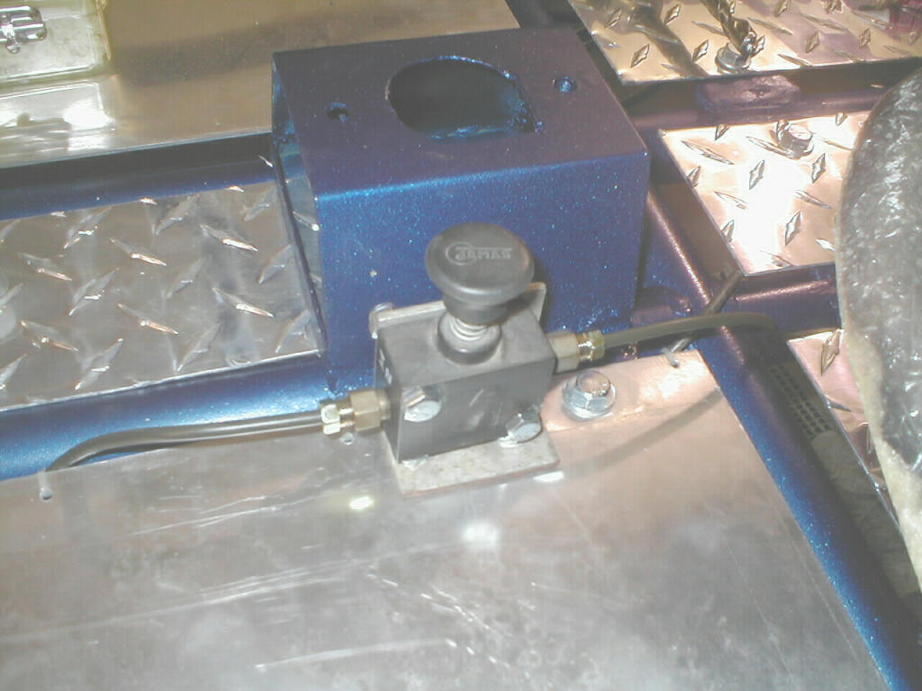
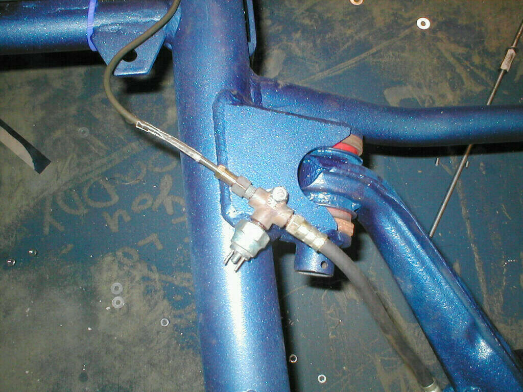
Next in line is the Jamar Park Lock. This serves as a parking brake, which is required for street legal applications.
Then the hard connections to the cutting brake. I like the addition of the bleeder valve, my old one didn't have this.
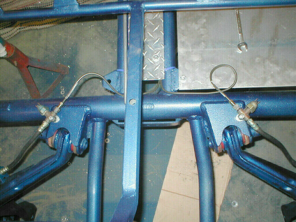
Here you can see the clutch line going back to where it will hook up the slave cylinder on the tranny.
And the brake lines running to either side of the buggy that will attach to the rear disc brakes that you will see later.
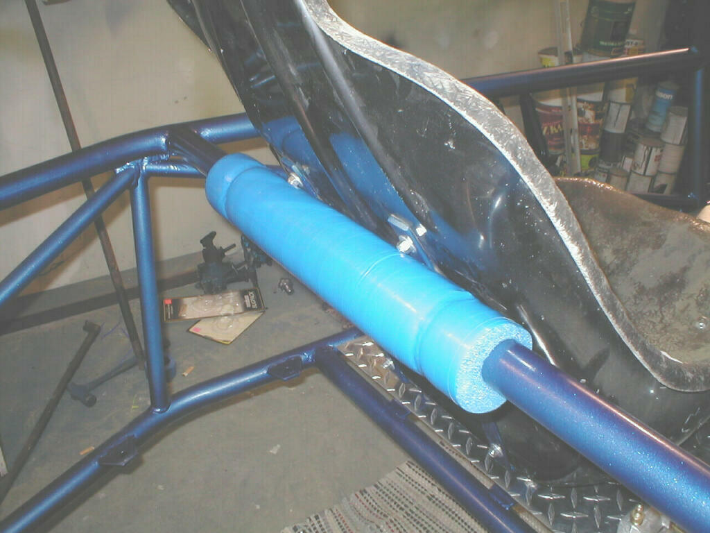
The next shot shows the padding I put behind the adjustable drivers seat to stop any contact with the paint.
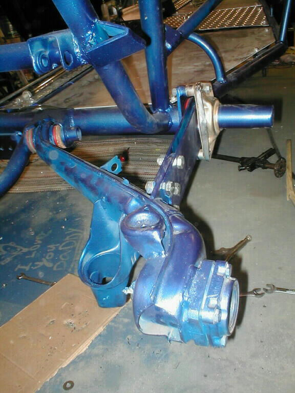
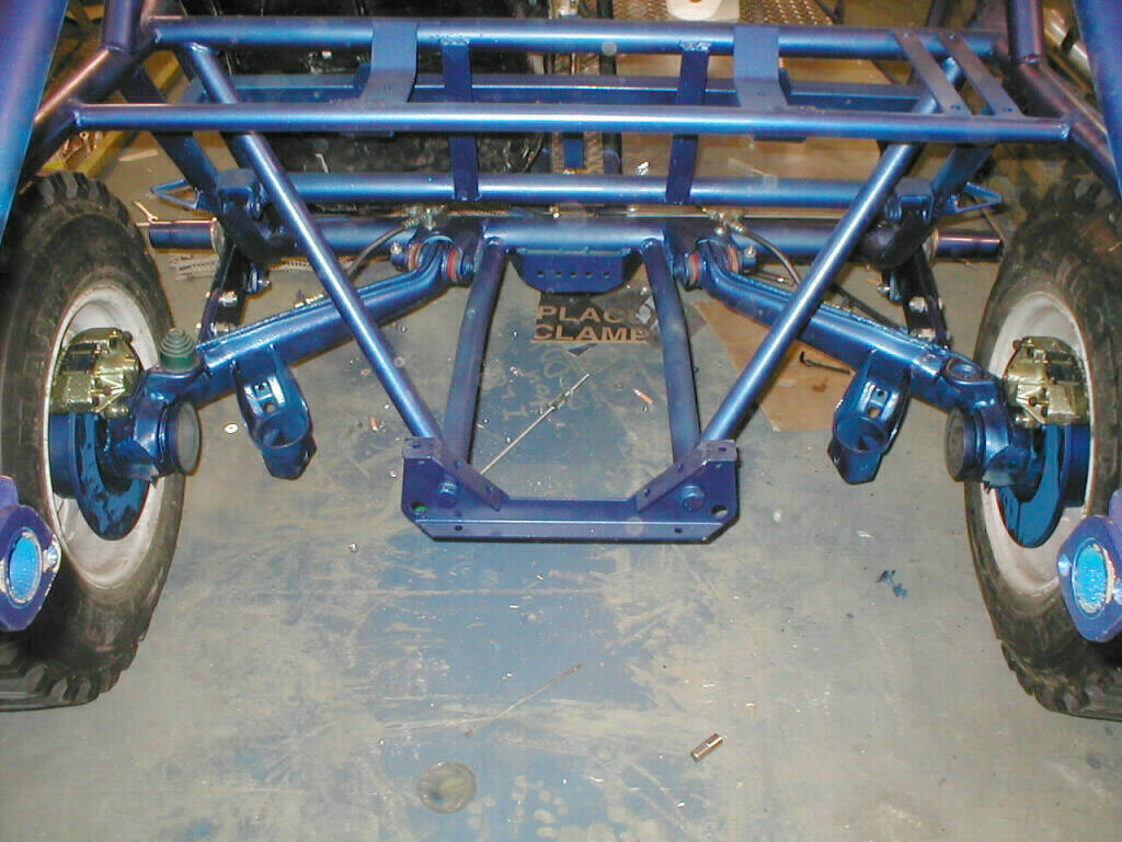
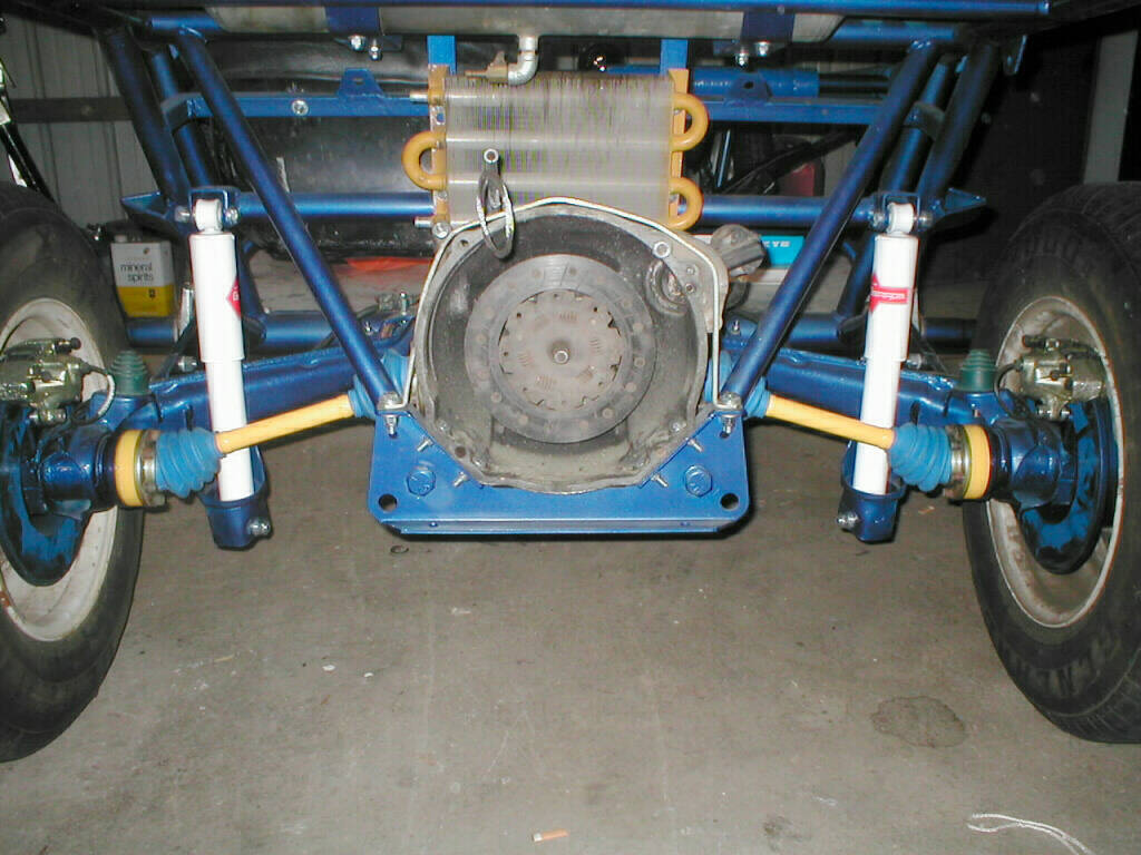
I installed the rear suspension, which is stock components attached to the custom torsion housing.
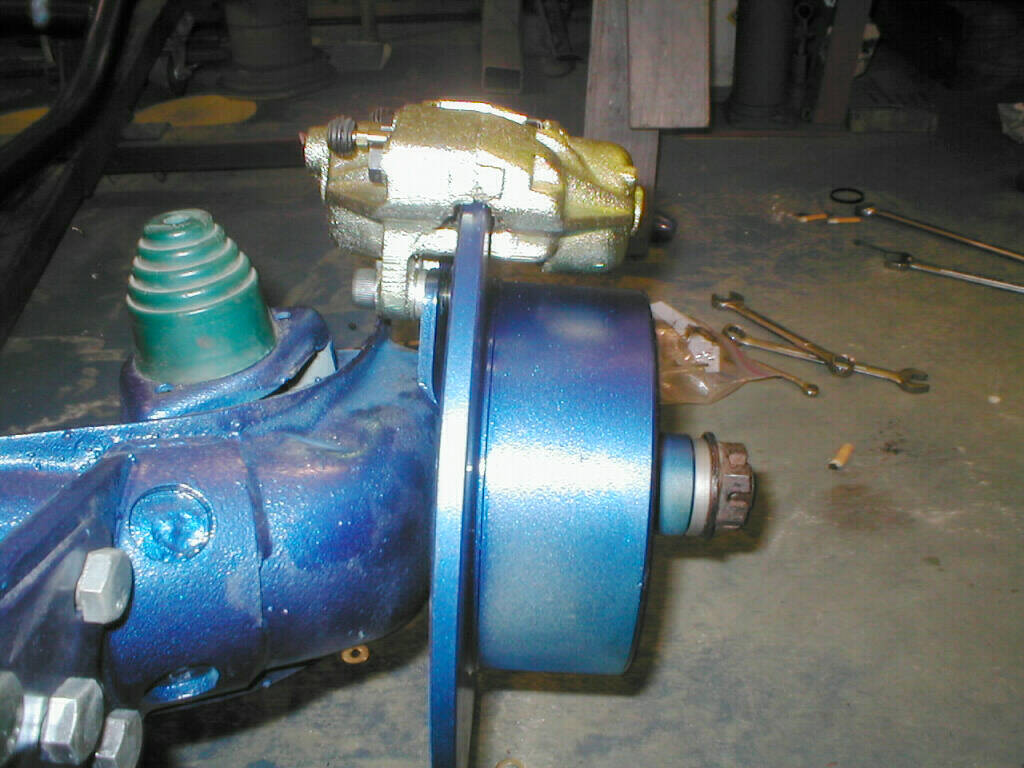
Once that was done, I was impatient to check out the fit of the rear disc brakes.
These brakes don't come with parking brake. I purchased them from The Latest Rage, in California.
Now (almost 2 years later) they are available almost every where, and are a lot cheaper.
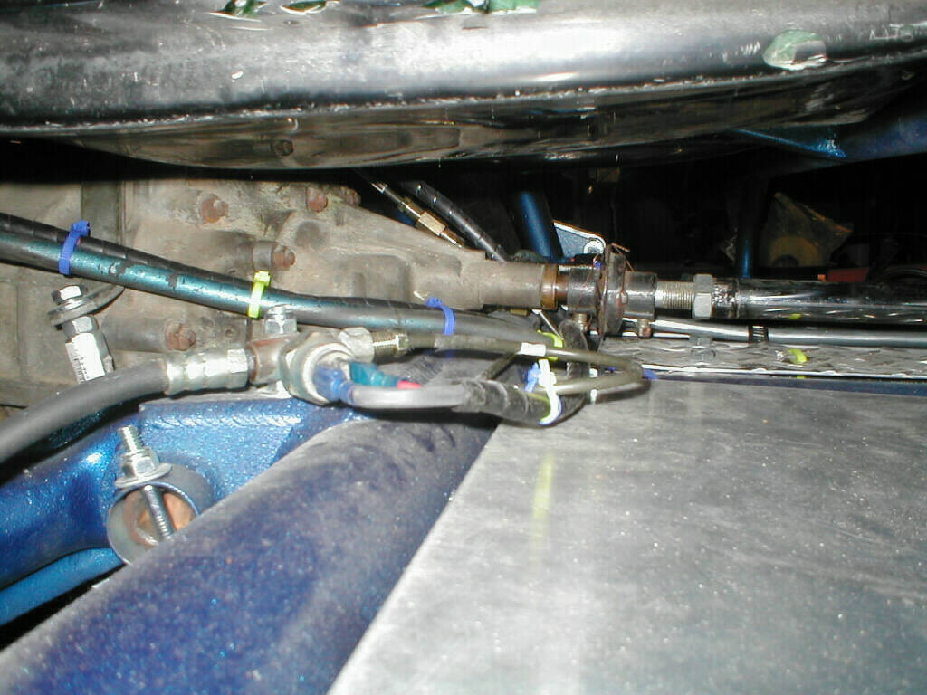
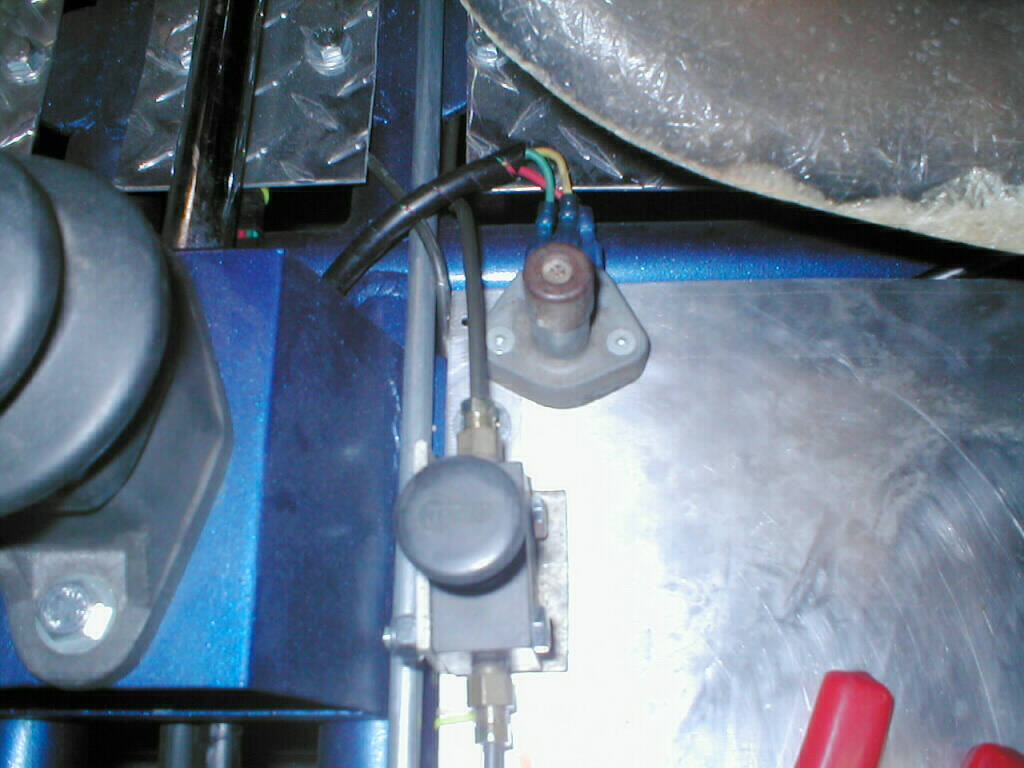
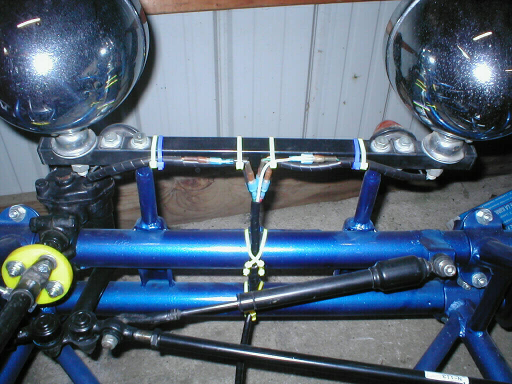
Here is the hook up for the rear brake with separate brake light sender units.
This activates both lights when the brake pedal is pushed and either light if the steering brake is used.
I used stock brake line tees, so I only had to adapt the brake line coming in, from bubble flare (stock metric) to double flare (SAE).
The rest of the fittings are stock bubble flare, including the brake light switch, rubber hose, and brake calipers.
On the left you see the rear suspension, brakes, and tires. This is the first time the buggy ever sat on it's own tires.
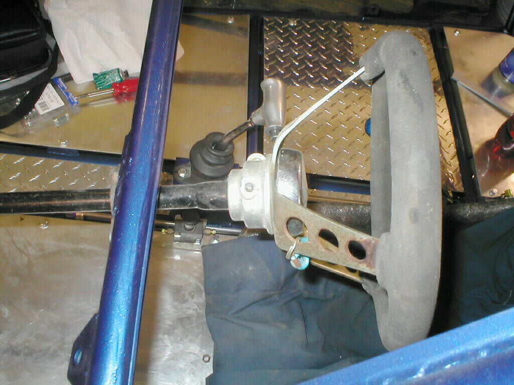
On the right is the shifter, bushing and shaft installed in the custom box I made and welded in earlier.
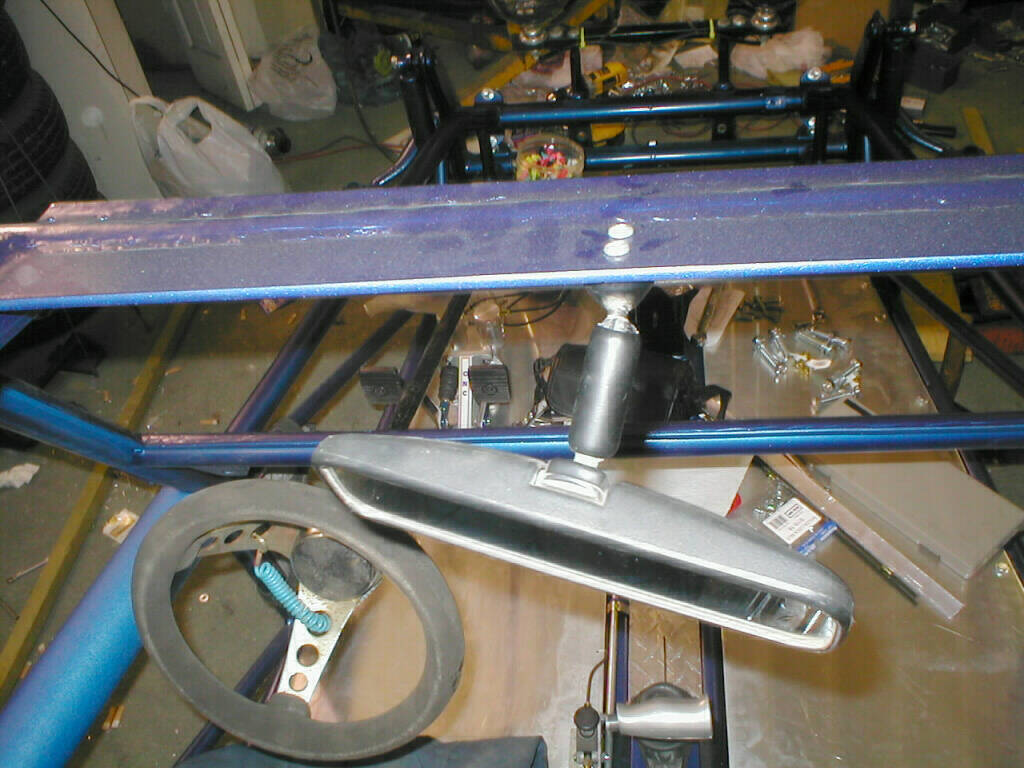
Next I mounted the rear view mirror to the flat stock I welded in for this purpose.
I could have mounted it to the windshield, but in my experience, that wouldn't hold up to off road fun.
The steering bearing and shaft is on the right. I have a quick disconnect steering hub to help with security when parked.
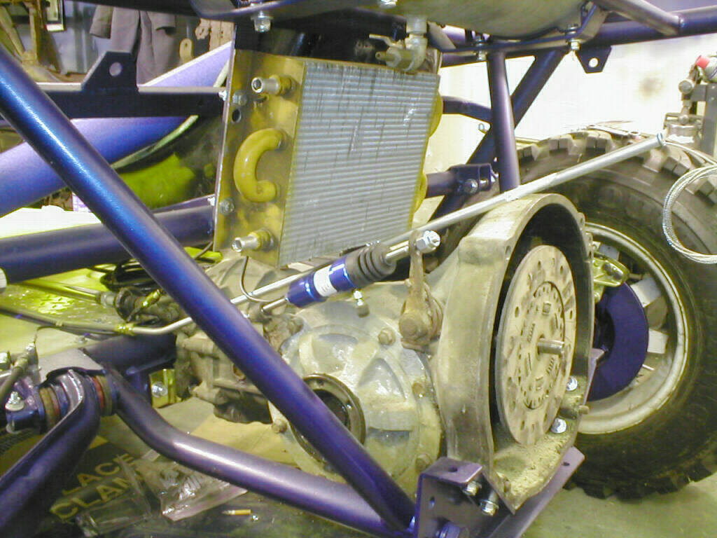
Transaxle (73 Type 4), clutch slave cylinder, oil cooler, and throttle cable all installed.
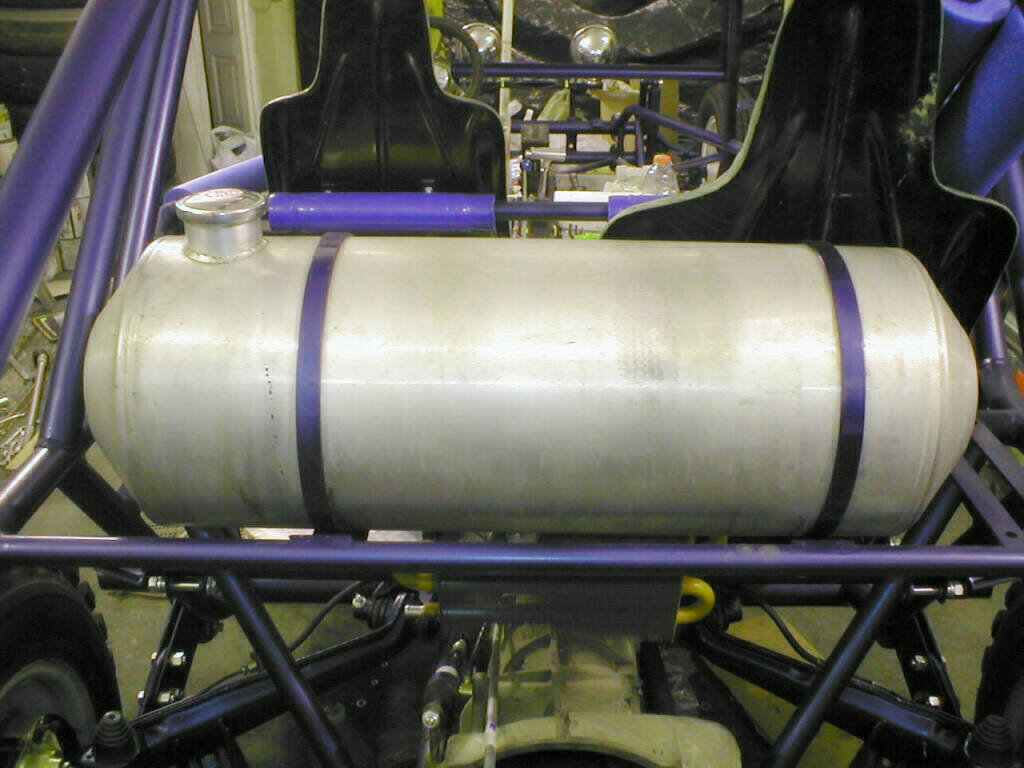
Gas tank (11" x 33", 10 gallon) mounted behind the rear seats and above the parts in the previous picture.
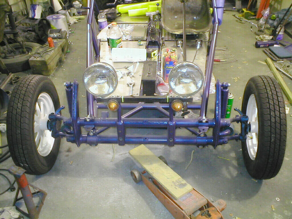
The front end mounted, with light bar (headlights and turn signals), painted KYB gas adjust shocks, blasted and painted spindle wheels sporting new P165 85 R15 tires.
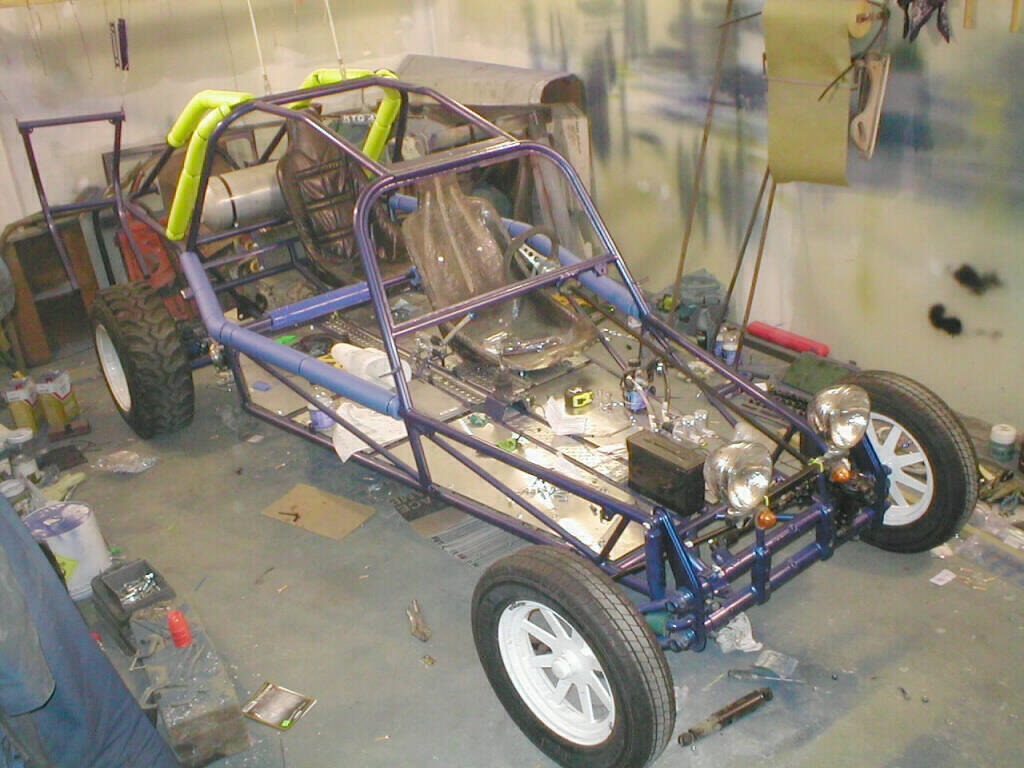
Finally sitting on it's own wheels!!!!! 55 caliber ammo box, used as a glove box, roll bar padding, and a test fit of the rear seat.
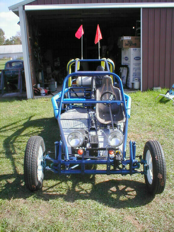
October 20, 2002 the first time it has been out of the barn. Don't let the sunshine fool you, the temp is only 40F. Well that's Michigan for you.
The reason I moved it out was to make room in the spray booth for winter storage, as you can see in the right hand pic.
Back in the barn, lots has happened ( I keep forgetting to stop to take pictures). Brakes complete and bled, tranny straps in place,
axles and CV joints repainted, new CV boots, new KYB gas adjust shocks, starter installed. That took about a week of evenings, working around every bodies schedule.
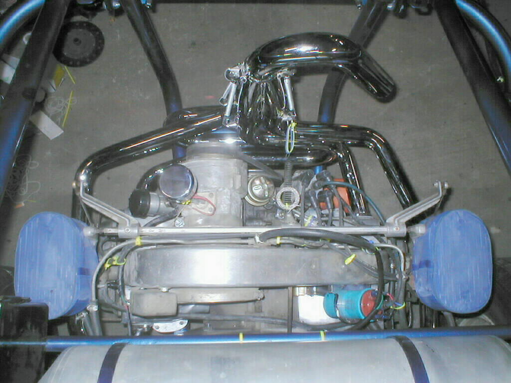
Next comes th motor. 1641cc, dual Dellorto 36mm carbs with hex bar linkage, Petronix ignition in a Bosch 009 distributor, sand sealed power pulley,
stock 74 ghia alternator with regulator mounted behind offset aluminum fan shroud, full flow oil filter pump for easy changes.
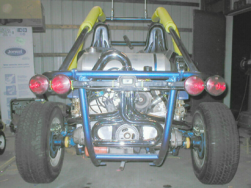
Inside the engine cage is a Tri Mill 1 5/8" chrome header exhaust with u-bend extractor. I went with the u-bend so that I didn't have to carry a cover for the exhaust.
I started wiring the buggy at the farthest point back, which is the oil pressure sending unit on the motor. Using spiral wrap I picked up all the other wiring along the way.
The first being the ignition and tach wires from the coil.
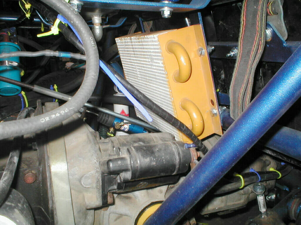
Along the back of the engine to pick up the wire form the alternator, down to starter to include the solenoid wire and the battery connection to the front of the buggy.
Next to these wires runs the positive battery cable (#2 welding cable). At the point that the wires go under the aluminum flooring, the rear light bar wiring also branches off.
This runs to the drivers side and back along the frame to a 4 way connector which attaches to the rear light bar.
The 4 way connector makes it easier to remove the engine cage, and provides a way to use the light bar as towing lights if you make your extension cable long enough.
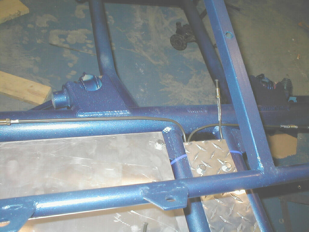
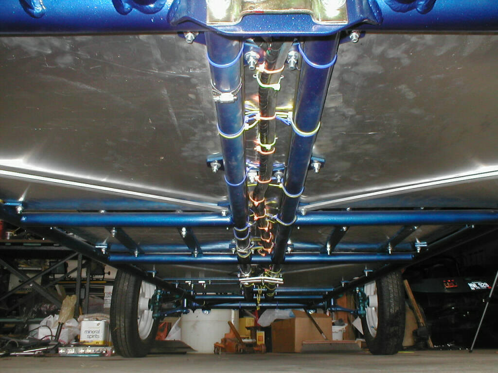
It's a little hard to tell from this pic, but all hydraulic and electrical connections run under the floor of the buggy, but up inside the frame.
This is to get a clean look but also so passengers (my kids) are not always stepping on every thing.
Here is my dimmer switch. It is a stock 65 VW floor mount dimmer, but I've mounted it to be activated by hand.
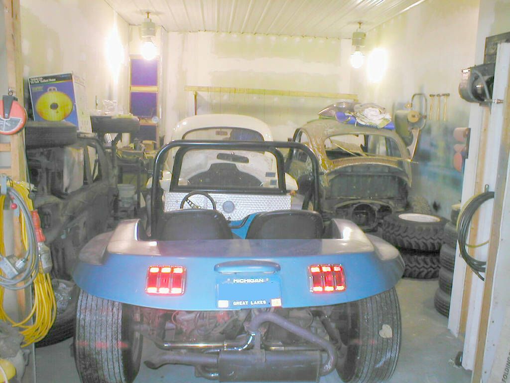
The light bar mounted and wired. It is a piece of 1" square tubing with the ends capped. All electrical connections are made to the back of the buggy now.
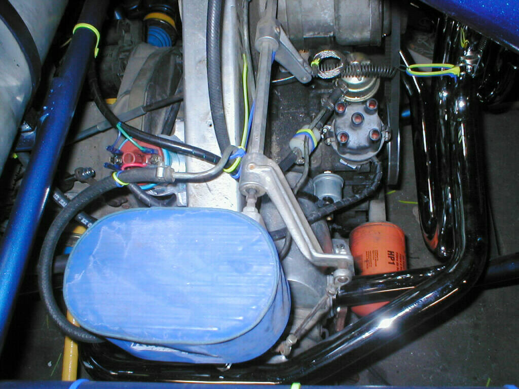
Right, the completely wired and plumbed motor just waiting for the rest of the electrical connection.
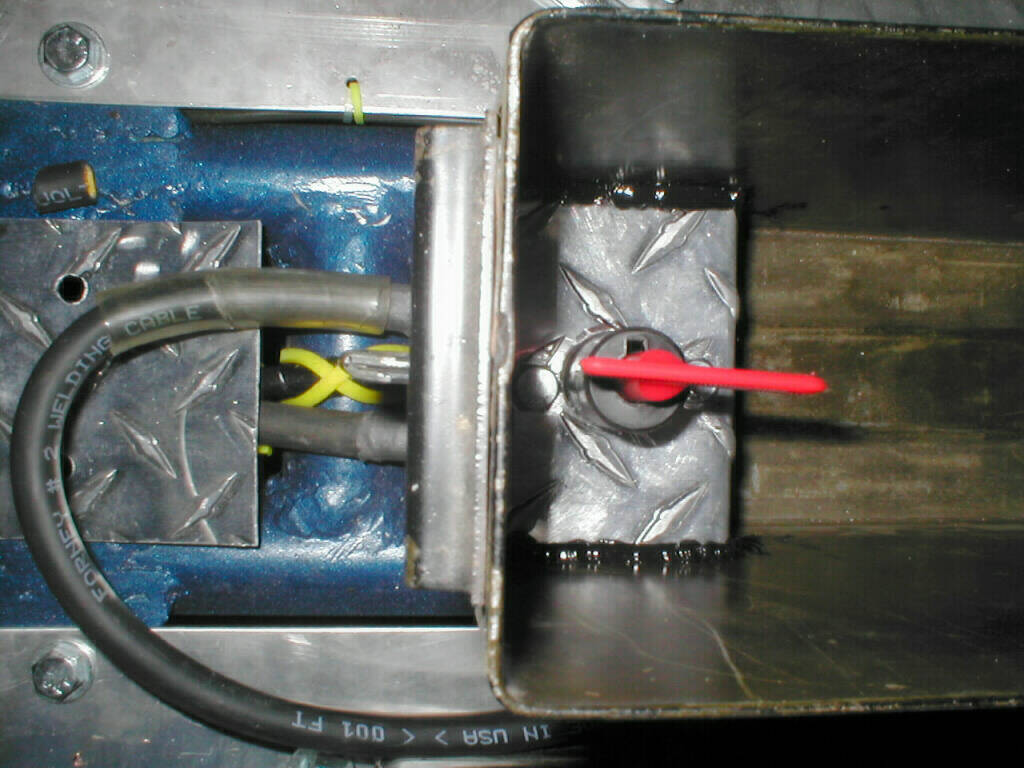
Left, again for security, I installed a battery disconnect switch inside my glove box. Since the switch is not sand sealed I mounted it inside the box.
Right, the wiring for the front light bar. Made from the same material as the rear.
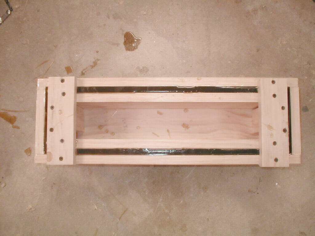
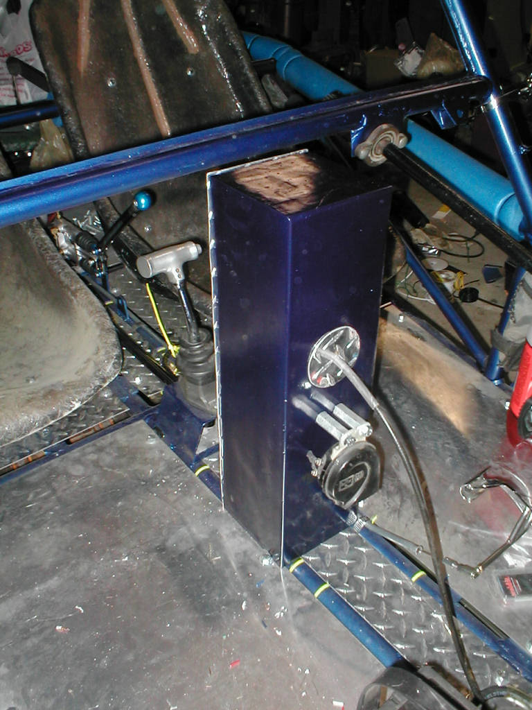
Left, I used 1x6 lumber to create the mold for my fiberglass instrument console. Before pouring the fiberglass, I put fiberglass mat in the mold to make the box stronger.
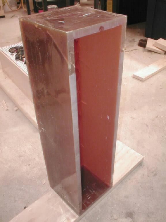
Right, the finished product. I did end up with a few cracks (because of the thickness of the mold) that I had to fill with more fiberglass.
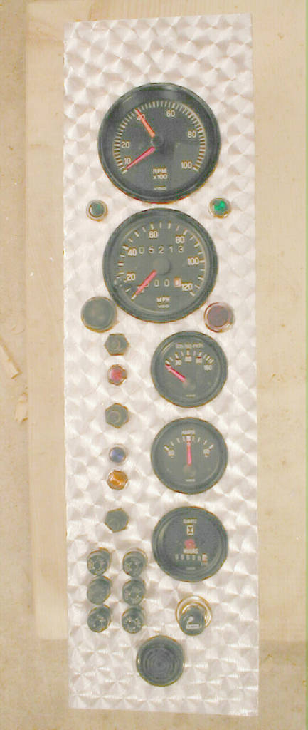
This is the gauge cluster that fits in the box. It includes, tach, speedo, oil pressure, amp and hours meters. Sand sealed switches for ignition, lights, turn signals, horn and indicator lights for everything.
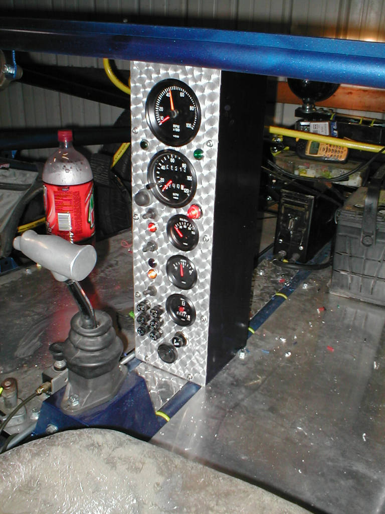
With the box sanded, primed, painted I installed it and the gauge cluster.
Left, another view of the console that shows the horn mounted and the speedo cable.
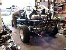
Right, Click on the picture to see the first time I started the buggy. That would be 11/15/02 at 4:30pm at a temperature of 33F. It will need some tuning in the spring, but I did take the family for a real cold ride.
Well, I hope to post more pictures in the spring when the temp is on the up swing.
Happy Holidays

Last revised on 11/16/02 ,by JA Novotny, using SiteAid 2.2